|
 |
 |
 | |||
  |
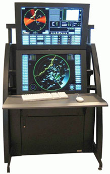
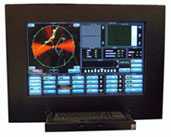
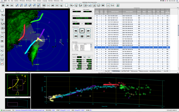
This software package performs aircraft tracking and statistical analyses on radar target data collected by the Hughes Air Defense Radar (HADR). Technical The software accesses the database of target reports generated by the radar. A sophisticated tracking algorithm converts raw target reports into aircraft tracks which are analyzed to calculate hit/miss ratios and probabilities of detection for the radar. Range, height, and azimuth errors are calculated and used to align the radar and improve performance. HED designs all of its software to make internationalization easy -- this software package can switch between English and Mandarin with a single button click. The software was written in C++ for both the MacOS and Windows platforms.
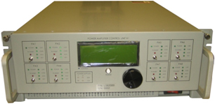
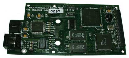
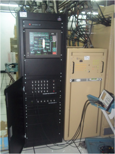
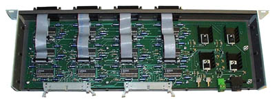
HED designed, built, and tested a custom Transmitter Control Unit to the monitor and control the transmitter subsystems for the Taiwan Hughes Air Defense Radar (HADR). Technical The TCU is based upon a custom data acquisition and control system paired with a COTS touch screen computer. The control system is comprised of custom digital, analog, and CPU boards all communicating over a custom backplane. An Ethernet interface provides communication between the control chassis, the touch screen PC, and an optional remote display/control console. Radars by their nature are pulsed systems and the DSP-based analog cards can perform real-time capture-and-intercept any pulse which might stress the transmitter. The captured waveforms can be later recalled on the display during troubleshooting and maintenance operations. The digital cards monitor a myriad of input signals and can turn off power and RF to prevent damage during real-time fault conditions. The digital output signals are used for normal mode and test mode control of the transmitter subsystem. A special built-in-test mode allows this system to fully control the transmitter during maintenance operations and a variety of front panel test points allow maintenance personnel to quickly analyze and debug transmitter problems. The touch screen GUI allows for intuitive monitoring and control of the transmitter. The GUI shows a block diagram of the transmitter subsystem where each component becomes highlighted during fault conditions. Touching a block diagram component brings up a detailed list of status and faults which allows operators to isolate and debug problems down to the LRU level. The GUI also contains a history of status and faults which can be viewed locally or on an optional remote display/control console.A half-rack-height door covers the control chassis and power supply during normal operation.
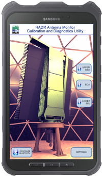
This system was designed for the Taiwan Air Force (Republic of China) to monitor subsystems inside of the radar antenna. Technical The Antenna Monitor added comprehensive remote monitoring of subsystems inside of the HADR antenna. Temperature, pressure, and flow rate sensors were added to monitor status of the antenna cooling system. Programmable fault limits prevent operation in the event of a cooling system failure, and time trending is used to detect degradation of performance and trigger preventative maintenance. A vibration monitor predicts mechanical failures in the coolant pump and heat exchanger fan to allow for preventative maintenance and reduced down time. A companion Android application allows users to monitor the status of the antenna using a tablet device via a Bluetooth interface.
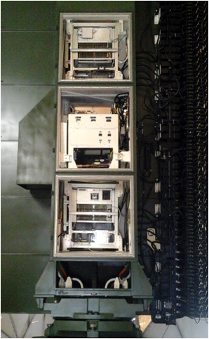
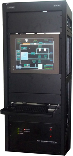
This system was designed for the Taiwan Air Force (Republic of China) to monitor and control two heat exchangers in the radar system. Technical The heat exchanger monitor samples sensor readings of flow, pressure, temperature and coolant resistivity at various locations in the cooling system and and inhibits operation of the radar in the event of a fault reading. A touch-screen GUI enables the user to view the status of the cooling system and to control the operations of the pump, fan and chiller.
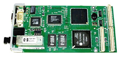
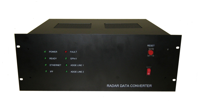
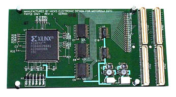
This system was designed for the Taiwan Air Force (Republic of China) to replace a PC based device that converts radar target reports in GFN-II format to DDL format, and to interface with the radar's Identification-Friend-or-Foe (IFF) system. Technical The Radar Data Converter contains an embedded Coldfire processor and interfaces to the radar system through a variety of serial and ethernet interfaces. The design includes a field-programmable gate array that implements a "de-fruiter" circuit to generate IFF video for display on the console
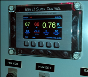
The Gen II Super Control is a user programmable industrial controller targeted to the wine industry. It is used to control the temperature of wine in fermentation tank as well as temperature, humidity, and CO2 levels in the areas where the wine is aged in barrels. Technical The controller can accommodate a variety of temperature, humidity, and CO2 sensors and provides on-off control to switch fans, pumps, humidifiers, heaters and valves. Up to five input sensors and five outputs are provided. The control is housed in a water-proof enclosure and features a color graphics display and a non-contact capacitive sense keypad. The design uses the PIC24FJ256 processor for display control and user interface, a Cypress CY8C21434 to impement the capacitive sense keypad, and a PIC24FJ128 processor for the control algorithms. HED designed this product for Refrigeration Technology Inc and has manufactured it in large quantities. The controller is in use at a number of wineries in Napa and around the world.
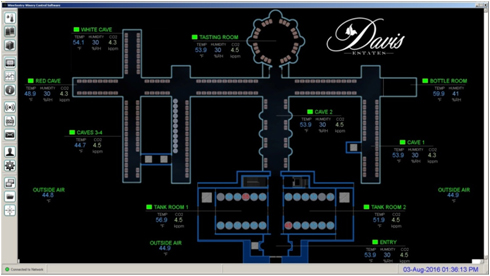
Talking in real-time to all industrial controls over a Modbus interface, this software allows for master control of all tanks and climate zones in the winery. The software collects and stores all process data, logs events, and monitors alarms. Users can be notified of alarms via text message or email, and the software serves up dynamic web pages for remote access from any smart phone or tablet device. Technical The software was written in C++ and is adapted to Windows, MacOS, and Linux platforms. HED designed this software for Refrigeration Technology Inc. It is currently in use in a number of wineries in the Napa Valley area.
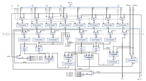
This custom chip implements the Scrypt algorithm used as proof-of-work required to mine the Litecoin digital currency. Technical The design features 128 cores each running the Scrypt algorithm for a total hash rate of 1.8 Mhash/second. The core implementation was designed using VHDL and tested on a Xilinx KC705 Evaluation board using the Kintex-7 FPGA. HED worked with ASIC foundries to have the chip manufactured. Due to the collapse of value of Litecoin, the chip was never built. If it had been, it would have significantly out performed other Litecoin mining chips on the market at the time.
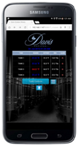
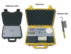
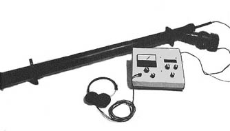
This product was designed for the electric utility industry. It allows them to determine the phase (A, B or C) of an unknown overhead or underground conductor in a three phase system. It is comprised of three units; The Reference Unit, the Field Unit, and the Hotstick. The Reference Unit gets installed (typically at a substation) on a known-phase conductor (typically phase A). The Field Unit is the yellow suitcase shown above and it is taken into the field where the utility linemen touch the companion Hotstick unit to an unknown conductor. The Hotstick sends wireless information to the Field Unit which in turn communicates with the Reference Unit to display the phase of the probed conductor. Technical The Field and Reference Units both contain GPS receivers which are used to measure the exact time between the zero-crossings of the AC voltage waveform, where the Field Unit is connected on a known-phase waveform to compare it against the unknown-phase waveform probed by the Hotstick. The Field and Reference Units employ cellular and landline modems respectively to exchange the timing information. The system can display which phase (A, B or C) is being probed and also the phase angle information (in degrees) on an LCD screen on the Field Unit. For safety considerations, the Hotstick is an inherently "ungrounded" system where the electrical path is completed to earth ground via the tiny capacitance which exists between the Hotstick enclosure and the earth.The Hotstick contains microprocessor based auto-ranging circuity which allows direct contact with voltages from 120V to 365kV. For more information or to purchase this product contact EDM International, Inc.
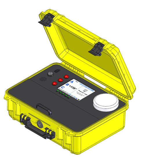
This product was the 2nd generation upgrade to the Phase Identification System designed by HED. Technical The 2nd generation design added a user friendly color touchscreen and graphical user interface, along with improvements to the Hotstick design, better phase identification algorithms and a digital communications link with the Reference Unit. For more information or to purchase this product contact EDM International, Inc.
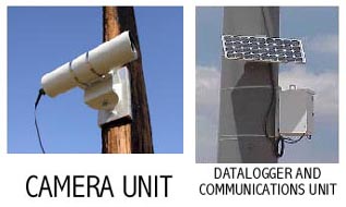
This product measures the amount of droop or “sag” on a high voltage power line. The amount of sag can be used to estimate the conductor temperature so that the line capacity can be maximized. Technical Although HED did not originally design this product, HED was enlisted to redesign the circuit boards internal to the Camera Unit and the Datalogger Unit. The redesign effort drastically reduced the amount of cabling and decreased the recurring cost of the product. For more information, or to purchase this product please visit www.edmlink.com/sagometer.html.
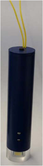
This device measures the volume and rate of urine flow and transmits the data wirelessly in real-time to the urology system computer. Technical HED originated the innovative enclosure design along with a custom strain gauge measurement controller with a Bluetooth communications link. The firmware features a specialized digital filter to accentuate irregularities in the urine flow rate. The firmware handles all communication protocols and controls the safe recharging of the batteries For more information or to purchase this product contact www.Life-Tech.com.
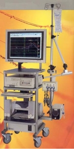
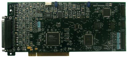
This product was developed for a medical instrumentation company specializing in urology. It upgrades their older ISA based data acquisition board to a fully plug-n-play compatible PCI based design. This board collects data from the clients “patient unit” for display and analysis on a PC. Technical This data acquisition board features 16 channels of analog input, each with programmable gain and offset. An analog output plus a digital data port and a one-shot output are used to interface with the customers external Uropump. In addition to I/O circuitry this design includes a 68HC908 processor, a PCI interface chip, and a custom CLPD design. On-board test signal generators and an audio monitoring port aid in system installation and calibration, and a 32K FIFO ensures continuous data transfer over the PCI bus. HED wrote a custom Windows device driver and INF file conforming to WDF (Windows Driver Model) standards. HED also supplied a custom Windows GUI to aid in product testing and evaluation. For more information please contact www.life-tech.com.
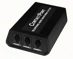
This product helps evaluate the training of telephone operators or telemarketers. The audio from up to three handsets is routed to the TAMS unit and a central monitoring office can call the unit to listen to any of the three handsets. Typically the monitoring office uses a PC to autodial all of the deployed TAMS units and automatically record the audio. That audio is then later evaluated to determine the effectivness of the training of the operator. Technical The TAMS employs an embedded controller coupled with a telephone interface and audio switching circuitry. Selecting the desired audio channel is accomplished using DTMF signaling from the monitoring office.
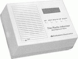
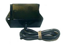
This product helps real estate agents sell homes. The agent can record a voice message describing the home for sale and the message is stored into digital memory and is transmitted on the FM band to passing automobile traffic. The interested home buyer tunes his car radio to the frequency posted on the for-sale sign to hear the message. Technical This product is superior to competitors products because it replaces the older unreliable tape loop with digital memory. This product digitizes the message using CVSD encoding and stores the data into RAM. A phase lock loop allows for precise setting of transmit frequency (88 to 108 MHz). A microcontroller handles all user input, PLL and CVSD programming, and drives the 4-digit LED display. The RF power output is kept low to allow FCC classification as an unlicensed transmitter. DC Power is supplied by a Wall Cube whose power lead serves as the transmit antenna.
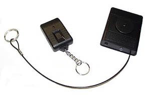
The "TAG" is a motion detecting alarm system for laptop computers and other high-dollar valuable items. It includes a keychain transmitter and an alarm unit. Once armed, any motion will cause the alarm unit to sound a piercing alarm tone that can only be reset using the keychain transmitter. Technical The 315 MHz coded signal from the transmitter is decoded and validated by an embedded microcontroller. If motion is detected while in the armed state a 100 dB alarm tone is produced by a piezoelectric annunciator. The wire tether attaches the alarm unit to the merchandise and also serves as the receiving antenna. The alarm unit is powered by a single AA battery which provides over 1 week of continuous use.
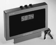
This product resides on the desk of the radio dispatcher for police, fire, or public or private utilites and displays a four-digit numeric ID of the person talking on the two way radio system. It is used to uniquely identify each radio transmitter in the customers fleet of vehicles or hand-held walkie talkies. Technical The ID1201 decoder processes the Motorola MDC1200 digital data burst that accompanies the audio of the transceiver. A PIC processor is used to decode the data stream and display the result on the four digit LED display. The ID1201 also includes a Xilinx gate array to aid in data decoding. The transceiver ID can also be sent to an optional printer or serial port. The ID1201 contains an embedded real-time clock so that the ID can be time and date stamped for printing. For more information or to purchase this product, please visit www.controlsignal.com.
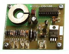
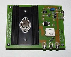
This product eliminates the need for the messy relief valve that expels hydraulic fluid when the hydraulic actuator encounters a heavy load. Technical The ERV monitors the energy being consumed by the DC motor of the hydraulic actuator and cuts off power if the motor load becomes too great or if the integrated energy exceeds a preset threshold. The later method of cut-off prevents motor overheating. The ERV is typically part of a control system that includes actuator buttons (Extend and Retract), a motor relay, and a DC power source such as a vehicle battery. The wire supplying current to the motor is fed through the circular torroid on the ERV which concentrates the induced magnetic flux across a hall-effect sensor. The PIC processor monitors the hall voltage which is in direct proportion to the current consumed by the motor. The ERV will open the external motor relay if the load becomes too great. The ERV can accomodate different sized motors from 20 to 100 Amps.
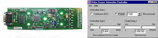
This product controls the electronic "shutter" of a high digital CCD video camera used primarily for microscopy. Technical This product incorporates a processor, high speed gate array, and precision D/A. The companion Windows based interface allows the user to control the Image Intensifier Gate, Gain, and Gate Delay. The Gate (shutter duration) can vary from 20nS to 1mS and can be delayed from an external trigger input (Gate Delay) which can vary from 0uS to 2mS in increments of 20nS. The Intensifer Gain can be set between 2500 and 80,000 foot-lamberts-per-foot-candle to equate to a 0V to 5V output. For more information or to purchase this product contact www.VideoScopeIntl.com
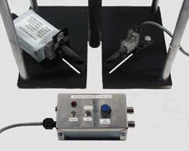
This product was designed for wind tunnel applications to accurately measure the amount of dust or dirt which might blow across a surface. Technical Comprised of an infared transmitter and reciever, this product can measure dust density over a 80dB scale (ratio of 1-to-100e6). The infrared transmitter LED can be either pulsed or on continuously and is controlled by circuitry housed in an enclosure shown in the bottom of the above photo. The receiver is based on a highly sensitive and large aperature infrared photodiode paired with a low noise logarithmic amplifier. The vertical tube in the assembly dispenses a known amount of "dust" and the electronic system measures the "down-wind" dust intensity. For more information or to purchase this product contact www.cppwind.com
This device was developed for audio laboratories (and for university physics laboratories) and allows the user to demonstrate the acoustical properties of various materials. By placing a test material inside the SWR resonance tube and measuring the standing wave minima and maxima, the absorption properties of the test material can be determined. Technical The Audio SWR analyzer is comprised of two components: the electronics module and the resonance tube. The electronics module contains a very high fidelity sine wave generator which drives a speaker via a low distortion amplifier. The speaker sets up a standing wave inside the resonance tube where a movable microphone inside the tube can locate the minima and maxima. The test sample is placed at the end of the tube and, depending on its acoustical properties, changes the minima, maxima, and phase when compared to a perfectly solid (reflective) test sample. The signal from the microphone is processed prior to being displayed on an analog meter. A microcontroller controls all frequency setting, frequency counting, and 5 digit LED display updates.
This circuit board allows for custom processing of discrete I/O signals in a Compact PCI computer system. Technical This product includes a Compact PCI interface and a custom gate array which allows the user to process discrete I/O signals in a variety of ways. It is housed on a PMC (PCI Mezzanine Card) circuit board and is compliant with IEEE1386. This circuit board typically resides on a VME form factor carrier.
This system allows two (redundant) computers to communicate on a single RS232 interface. It overcomes the "one DTE per interface" limit by incorporating bridge circuitry. The system can handle up to eight RS232 interfaces and is housed in a 19 inch rack mount panel.
This product was developed for a railroad remanufacturing company. This circuit is part of a control loop which allows a PC computer to set the current in an exciter coil of a DC generator. Technical This relatively simple analog circuit uses a precision current monitoring technique and provides excellent linearity and temperature stability. It is designed to be mounted inside the customers generator control panel.
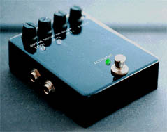
Built for the electric guitar industry, the "HeadRoom" product can greatly enhance the artistic ability of the musician. Technical This device restores the dynamic range which is lost when an electric guitar is played through a distortion box. It employs precision analog multiplier circuitry which samples the raw guitar input and varies the distortion box output accordingly. The ratio of input to output (the slope of the response) is adjustable to accomodate user preferences. Other controls allow for compatibility with all types of guitar pickups and distortion box outputs.
This device was designed and mass produced for the United States Postal Office and is part of a vehicle identification and location system. Technical This circuit contains a highly sensitive motion detector whose output is processed by an 8 pin embedded microcontroller which implements a custom filtering algorithm that reliably declares motion in a variety of deployment situations (parked with engine running versus actual driving). The output is used to enable power to a cellular data link and GPS based vehicle tracking system. The circuitry includes automotive regulators and surge supression devices to ensure reliable operation in an automotive enviornment.
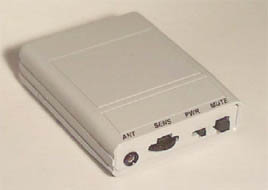
This product was developed for the countersurvellience industry and will "buzz" the user when a UHF or VHF body wire transmitter is operated nearby. It is the worlds first pager sized RF detector. Also available in a discrete black plastic enclosure. Technical This device is a wideband RF detector and boasts the industry's best sensitivity of -70 dBm at 500 MHz due to a logrithmic RF detection scheme. It contains a microcontroller which handles duty cycling of the receiver circuits, and can run for over 2 weeks on a single AA battery.
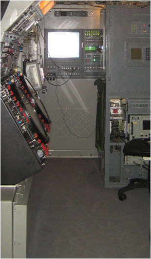
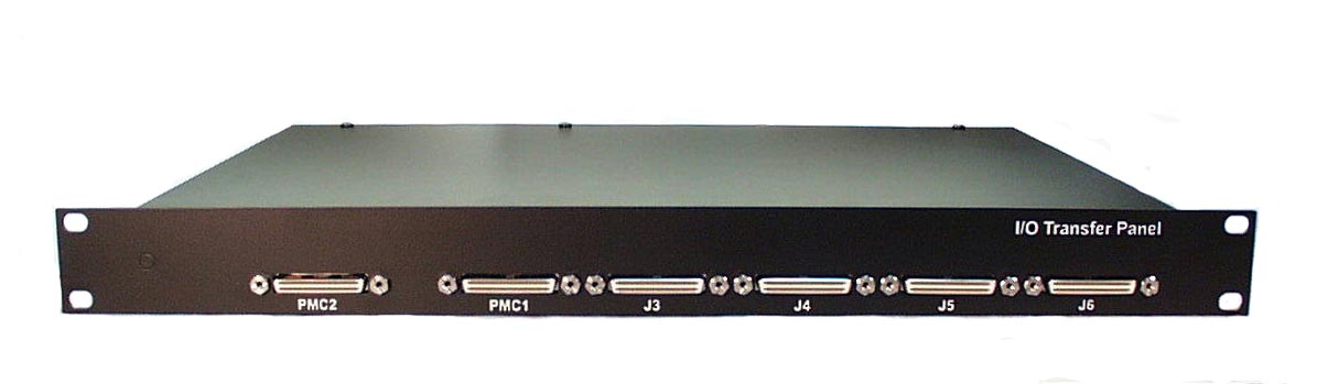
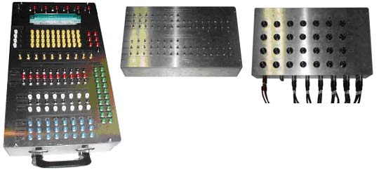
This product was developed for Raytheon Technical Services and is used to aid in upgrading their radar installations in Taiwan and Germany. The I/O Transfer Panel is housed in a 1U rack mount enclosure and allows the installer to reroute hundreds of signals and serial interfaces using a jumper field.
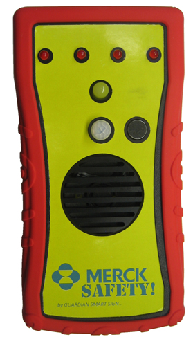
The Smart Sign is a safety product that plays audible safety messages any time nearby motion is detected. It can be placed wherever a safety hazard might exist, such as on a �wet floor� sign, door knob to a quarantined room, or other location. It includes an auto-shutoff feature which turns off power after a user-preset time of 30, 45, or 60 minutes has elapsed. This allows time for the floor to dry or hazard to be removed. The auto-shutoff can be disabled for use in areas that don�t need to be timed such as on-going construction sites. The absence of the flashing white light and audio message indicates to passers-by that it is safe to enter the area. Technical The Smart Sign can store up to four different messages where each message can be a maximum of eight seconds in length. Each time motion is detected the recorded messages are played back, one at a time, in a rotating fashion. Multiple messages can be beneficial in multi-lingual environments. For example, message #1 could be the English Caution, Wet Floor followed by message #2 in Spanish Cuidado, Piso Mojado A bright white light flashes every 5 seconds providing a visual indication of the nearby hazard. If only one message is recorded, that single message will be played back each time motion is detected. So as not to unduly annoy passers-by, five seconds of silence is enforced between the message(s) being played back.
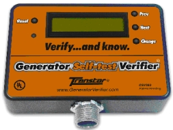
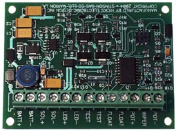
This product is mounted to a generator control panel where it continuously monitors the three phase generator output to determine whether the stand-by generator successfully performed its periodic auto-start self test. If the generator failed to start in the prescribed interval an audible alarm is sounded and accompanying relay is closed. The internal relay may be connected to a remote monitoring system to alert maintenance personnel of the generator fault condition. Technical An embedded microcontroller samples the analog voltage output from the generator and in addition to the generator start/no-start condition it also serves as an undervoltage/overvoltage detector. The self test interval is jumper programmable for 8/15/22/32 days and the expected generator output is programmable for single phase or three phase systems ranging between 120-480 VAC. This product is currently manufactured by HED in high volume for Transtar Products, Inc. For more information or to purchase this product contact www.GeneratorVerifier.com.
The GSV300 represents a substantial technology improvement over the previous model, the GSV200. The new model features a large LCD display, easier setup, and greatly enhanced features. The GSV300 monitors a standby generator and determines whether it fails to perform it's periodic self-test. It works on any generator with voltage output between 120-480VAC and also works with �Low-RPM� or �Quiet� type generators. Technical This system contains an embedded microcontroller, real-time-clock, LCD display, and analog signal conditioning. It samples the analog voltage output from the generator and utility to determine whether the generator failed to perform it�s periodic self-test. The system also serves as a voltmeter, frequency meter, oil change reminder, and run-time hours meter. It has four relay outputs which can be connected to an external monitoring system to remotely inform the owner of generator health and status. This product is currently manufactured by HED in high volume for Transtar Products, Inc. For more information or to purchase this product contact www.GeneratorVerifier.com.
This product was developed for a gas and oil drilling company. The circuit controls a latching solenoid which bleeds off accumulated water when the water float switch reaches a predetermined height. The solenoid open-to-close duration is adjustable between 1 and 20 seconds using a potentiometer. Technical This circuit contains a DC/DC converter, H-Bridge, and microprocessor. The circuitry was designed to have extremely low power consumption and will last for more than three years when powered from a standard 6V alkaline lantern battery.
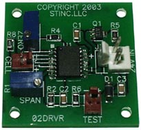
This product was developed for an environmental engineering company. The circuit converts the signal from an oxygen sensor to a 4-20mA current loop signal for remote monitoring. The sensor zero and span are adjustable using potentiometers.
HED manufactures a variety of test fixtures and test �boxes� to support our in-house projects, or as separate projects where the test equipment is designed and built per customer specifications. Test systems can be basically passive (containing only switches, connectors, controls, etc) or active (containing custom circuit boards in addition to passive circuitry).
This circuit board is a good example of HEDs capability to reverse engineer and redesign obsolete circuit boards or systems. We address obsolescence issues and redesign using current technology (the circuit board shown above was originally a wire-wrap design comprising two separate circuit boards).
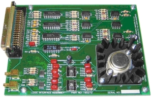
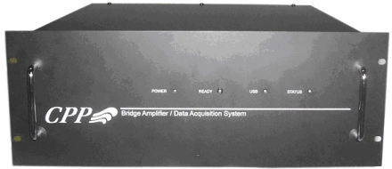
This device is a high precision, rack mount, 16 channel, USB-based strain gauge measurement and data logging system. The system features programmable DSP-based filtering of the strain gauge signal so that any customer-defined filter can be implemented. Technical Other features include a programmable strain gauge excitation voltage of 5V, 10V, or 20V with extremely small excitation ripple, and can accommodate any strain gauge between 350 and 2000 Ohms. The amplifier gain can be varied between 1 and 10000 in 1:2:5 step increments with the resulting noise being less than 20mVp-p at max gain of 10000. Any offset inherent to the strain gauge can be zeroed using coarse and fine offset adjustment controls. BNC outputs of the pre-filtered signal allow for external signal filtering and an optional external sample rate clock can be injected for synchronization with other subsystems. The system employs industry standard XLR connectors for the strain gauge interface. For more information or to purchase this product contact www.cppwind.com. |
|||||||||||||||||||||||||||||||||||||||||||||||||||||||||||||||||||||||||||||||||||||||||||||||||||||||||||||||||||||||||||||